Membrane Learning Center
Welcome to the Membrane Learning Center, where you can read about membrane filter characteristics and their impacts on your processes. This knowledge, which has been gleaned from decades of research, can help you choose the best filter for your application.
How to Choose the Best Filter for Your Process
To select a filter, ask yourself the following five questions:
- What are you filtering? Determine:
• Size and nature of the particles or molecules to be removed
• Chemical composition
• Volume - What pore size or nominal molecular weight rating (NMWL) is required to achieve separation?
- Will this be a sterilizing filtration?
- How quickly do you need to filter? I.e., what is the volume and available processing time?
- Will you use pressure-driven or vacuum-driven filtration?
By answering these questions, you can improve your chances for obtaining precise, accurate separation of your sample, chromatographic mobile phase or other liquid.
Explore the rest of this learning center for detailed information on membrane characteristics and some of the tests we perform to ensure that each filter matches our stringent quality specifications.
MEMBRANE WETTABILITY CHARACTERIZATION
For liquid filtration, a membrane must be wettable with the fluid being filtered. The wettability of a membrane is tied to the chemical properties of the membrane surface. Most polymers used to manufacture microporous membranes are naturally hydrophobic, meaning they will not wet out with water.
Some exceptions are nylon and cellulose which are naturally hydrophilic and will wet out with water. The distinction between hydrophobic and hydrophilic relates to the surface energy of the polymer. If the surface energy is >70 dynes/cm, the polymer is hydrophilic. Below 70 dynes/cm, the polymer is hydrophobic.
A hydrophilic membrane is wetted by water / aqueous solution whereas a hydrophobic membrane is wetted by organic solvent as shown in the figure below.
If a hydrophobic membrane is required for filtration of aqueous solution, it can be wet first with the alcohol and then equilibrated in water prior to filtering the aqueous fluid. In most cases this is not feasible and hence hydrophilic membranes are required for filtration of aqueous solutions.
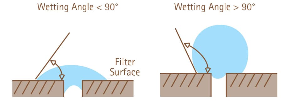
Figure 1The angle that is formed by the edge of a water droplet on a horizontal membrane defines wettability. On a hydrophilic membrane (left), the wetting angle is less than 90 degrees, while on a hydrophobic membrane (right), the wetting angle exceeds 90 degrees.90 degrees.
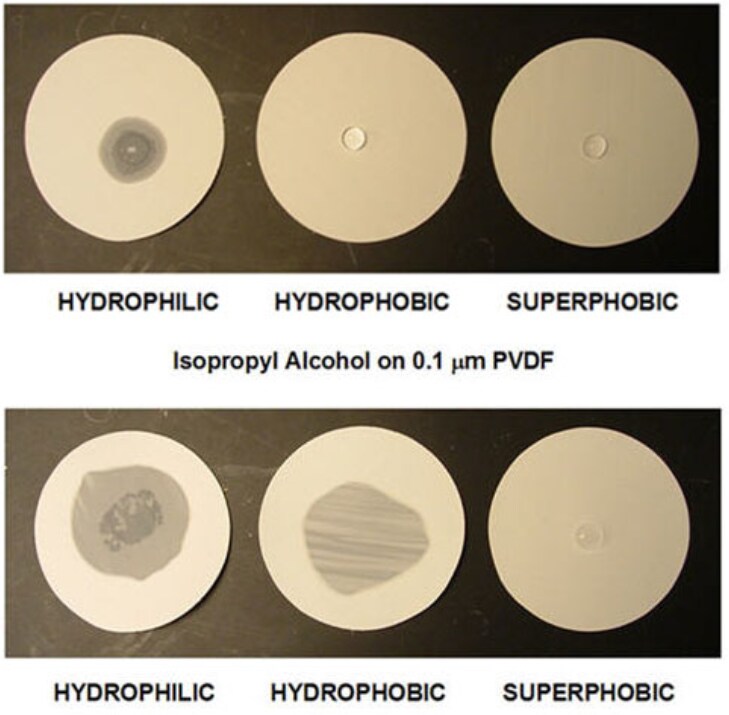
Figure 2While a drop of water can wet out only a hydrophilic membrane, rendering it translucent, a drop of isopropyl alcohol can wet out both hydrophilic and hydrophobic membranes, but not a superhydrophobic membrane.
Overcoming Hydrophobicity
To overcome the hydrophobicity of the polymer, the membrane can be treated with a secondary chemistry that coats the base polymer. The secondary chemistry becomes primary in determining wettability. It is important to recognize that the base polymer remains hydrophobic unless the secondary chemistry is a covalent modification of the polymer.
Membrane Coatings to Change Wettability
Hydrophilic membranes wet spontaneously with pure water (at a surface tension approximately 72 dynes/cm2 at ambient conditions) and require some elevated pressure to allow intrusion of water into the pores of the structure. Reduction of surface tension of the wetting fluid either through addition of solutes, such as surfactants or low surface tension miscible solvents such as alcohol to water, will have an impact on how quickly dry membranes will wet.
In addition, solvents or solvent mixtures which possess a relatively low surface tension will wet hydrophobic membranes spontaneously.
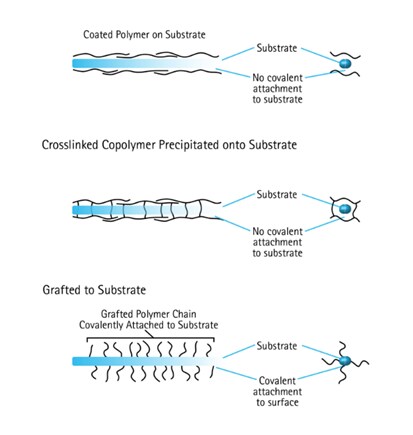
Figure 3Three ways that a membrane can be treated with a secondary chemistry to change its wettability.
Venting
In venting applications, the filter is used as a porous barrier that allows escape of gas bubbles from a liquid stream or exchange of gases between a liquid stream and the external atmosphere. To ensure that the filter does not wet out under any circumstances, it can be treated with a secondary chemistry that renders it superhydrophobic or oleophobic. This reduces the surface energy to <20 dynes/cm. The membrane cannot be wet with water or alcohols.
MEMBRANE PORE SIZE OR NMWL
Pore size relates to the filter’s ability to filter out particles of a certain size. For example, a 0.20 micron (µm) membrane will filter out particles with a diameter of 0.2 microns or larger from a filtration stream.
Pore size is determined by one of several techniques:
- Visual examination using scanning electron microscopy, where a small section of membrane is appropriately treated, put in the microscope, and evaluated, using appropriate imaging software.
- A bubble point test measures the minimum pressure required to force liquid out of the membrane pores as an indirect survey of pore size. Liquid is held in the pores of the filter by surface tension and capillary forces. The minimum pressure required to force liquid out of the pores is a measure of the pore diameter.
- Destructive bacterial challenge testing can be used to determine a sterilizing filter's ability to retain bacteria. Nondestructive testing may be done on filters before and after use to measure integrity.
- Porosimetry is a physical method where liquid is forced into the membrane under pressure and the penetration profile is analyzed mathematically to determine pore size.
- Particle challenge uses particles of defined size to determine the minimum size that can be retained by the filter
With ultrafiltration (UF), filter pore size is irrelevant because the pores are so small. These filters are rated according to their nominal molecular weight limit (NMWL) or their molecular weight cutoff (MWCO). For example, a UF membrane rated at 30,000 will exclude a test protein with a molecular weight of 30,000 Daltons. Ninety percent of that test protein will be retained on the upstream side and 10% will pass through into the filtrate, resulting in concentration of the protein. Ultrafiltration membranes are typically assessed using a mixture of dextrans as an industry standard for MWCO.
Although all membranes are rated for a particular pore size, pore size ratings alone are an unreliable measure of filter effectiveness because these ratings vary from manufacturer to manufacturer and from product to product. The function of the filter – is it a prefiltration, clarification, or sterilization filter, for example - and how well the filter performs that function need to be considered.
Bubble Point Integrity Test
Bubble Point is a practical, nondestructive test used for estimating the pore size of microporous filters and confirming the integrity of sterilizing membrane filters and filter systems. It is the most widely used non-destructive integrity test.
Bubble point is based on the principle that liquid is held in the pores of the filter by surface tension and capillary forces. The minimum pressure required to force liquid out of the pores is a measure of the pore diameter. The pressure required to force liquid out of a liquid-filled capillary must be sufficient to overcome surface tension and is a direct measure of effective tube diameter.
Formula for Bubble Point Test
Where:
P = bubble point pressure
d = pore diameter
k = shape correction factor
cos θ = liquid-solid contact angle
σ = surface tension
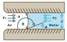
Figure 4. Diagram showing derivation of bubble point test formula.
The bubble point test is a sensitive visual technique and is performed routinely as part of our Quality Assurance Program. The bubble point test detects minor filter defects and out-of-size pores and correlates with the bacteria passage.
Bubble Point Procedure for Filters
1. Wet the filter with the appropriate fluid, typically water for hydrophilic membranes or an alcohol for hydrophobic membranes.
2. Place the filter into the holder and cover the membrane with the wetting fluid.
3. Pressurize the system to about 80% of the expected bubble point pressure which is stated in the manufacturer’s literature.
4. Slowly increase the pressure until a single, continuous stream of bubbles comes through the membrane.
5. Read the bubble point pressure from the pressure gauge.
Bubble Point Procedure for Device Integrity
1. Wet the filter with the appropriate fluid, typically water for hydrophilic membranes or an alcohol/water mixture for hydrophobic membranes.
2. Pressurize the system to about 80% of the expected bubble point pressure which is stated in the manufacturer’s literature.
3. Slowly increase the pressure until rapid continuous bubbling is observed at the outlet.
4. A bubble point value lower than the specification is an indication of one of the following:
- Fluid with different surface tension than the recommended test fluid
- Integral filter, but wrong pore size
- High temperature
- Incompletely wetted membrane
- Non-integral membrane or seal
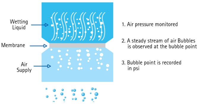
Figure 5.Bubble point test procedure for devices
MEMBRANE FLOW RATE
Flow refers to the time it takes for a particular flow stream to pass through the filter. The flow rate of a filter is important in determining how rapidly filtration can be completed. Although flow rate generally decreases with pore size among membranes of a single type, membranes with the same pore rating, but made from different materials or by different methods, can have very different flow rates. Flow rate differences can be caused by differences in thickness, porosity, and pore architecture.
After a microporous membrane is produced, flow rate or flow time is measured using an ideal liquid or gas. Hydrophilic filters are usually tested with water. Hydrophobic membranes are usually tested with an alcohol. Membranes to be used for air filtration can be tested with dry air or dry nitrogen. By using ideal liquids and gases, the flow properties of the filter can be assessed independently of particulates or other contaminants that could clog the pores. If there is nothing in the sample stream to clog the pores, the flow rate should remain constant. For ultrafiltration, there are special considerations on flow rate.
Flow Rate and Ultrafiltration
During ultrafiltration, it is important to balance flow rate with retention to obtain optimal performance. With ultrafiltration membranes the term more commonly used is flux. A membrane’s flux is defined as flow divided by the membrane area. The reason that flux is used with ultrafiltration membranes is the need for scalability. Ultrafiltration membranes are commonly used in the purification of expensive biomolecules. Separations are investigated on a small scale in the laboratory before being scaled up to larger volumes in a production setting. Characterizing separations on the basis of flux makes is easier to convert a lab scale investigation to a production scale process.
Using membranes with higher NMWL ratings will increase the flow rate, but at the same time lower the retention. A membrane should be selected for the required retention, coupled with the desired flow rate. This is determined by:
- Surface area
- Macrosolute type
- Solubility
- Concentration and diffusivity
- Membrane type
- Temperature effects on viscosity
- Pressure
When concentration polarization is rate-controlling, flux is affected by solute concentration, fluid velocity, flow channel dimensions, and temperature.
Air and Gases
Since sterility is a common requirement of vent membranes, pore rating is an important consideration. Please note that the mechanism of bacterial retention by hydrophobic membranes in a gas stream differs from that for hydrophilic membranes. Bacteria and other pathogens float in air attached to particles (aerosol or dust). Consequently, in air filtration, pathogens can be rejected by membranes with pore sizes larger than the pathogen alone. Membranes with pore sizes up to 5.0 µm are claimed to exhibit >99.99% bacterial retention efficiency by some suppliers. Similar claims exist for viral retention on 0.2 µm membranes. Therefore, membranes with larger pore sizes are used in less critical applications, yielding the benefits of higher flow rate.
When comparing the air flow rates of different membranes, it is important to note the units in which flow rate is reported and any differences in the conditions under which testing was done. Small changes in pressure and temperature can dramatically affect reported air flow rates.
Liquid
Liquid flow is measured by placing the filter into an appropriate holder, adding a defined volume of liquid to the holder, and then pulling the liquid through the filter with a constant vacuum. Flow thus depends on the nature of the liquid, the surface area of the membrane, and the vacuum level. To compare different membranes, the same liquid and vacuum level should be used.
While water and alcohols can be used to test flow rate in large scale testing, they may not provide enough discrimination in predicting membrane performance when a more complex solution such as serum or cell culture medium is to be processed. For specific applications, it is appropriate to use other test solutions. Since complex solutions, such as cell culture media, are considerably more expensive than water or alcohols, sampling plans and test protocols should balance the amount of extra data required against the additional cost.
BINDING PROPERTIES OF FILTERS
If you are filtering a sample containing analytes or other valuable components of interest, you need to be confident that these analytes are not lost by binding to the filtration device, and that the molecular composition of the filtrate is what you expect.
Analyte binding depends on the characteristics of the analyte and the properties of the membrane and prefilter. Molecular structure of the analyte as well as the membrane will give an indication of which interactions to watch out for. The nature of the interaction between a drug and a surface depends upon the functional groups found on the surface. The most common interactions are hydrogen bonding, hydrophobic interactions, and electrostatic interactions. While electrostatic interactions are quite strong, these are dependent on charges on the analyte as well as the membrane surface. Hydrogen bonds are weaker than electrostatic interactions but can vary widely based on the nature of the filter membrane material and whether it is a hydrogen bond donator or acceptor. Hydrophobic interactions are generally weakest.
Because the internal surface area of polymeric microporous membranes is 100–600 times as great as the frontal surface area, there is a vast internal surface area available for nonspecific binding. Both hydrophilic PTFE and Durapore® PVDF membranes have very few functional groups that can interact with various analytes, thereby leading to low analyte binding and subsequently high recovery. Nylon membrane contains amino and carboxylic acid functional groups as well as amide bonds which can interact with acidic or basic analytes through electrostatic and hydrogen bonding interactions, leading to high analyte binding and low recovery.
Of all membranes evaluated, the hydrophilic PTFE and hydrophilic PVDF membranes were found to be extremely inert and exhibited both the lowest protein binding properties and the highest product recovery. Hydrophilic PTFE is generally recommended for filtration of low molecular weight analytes, while hydrophilic PVDF membranes are recommended for filtering protein and biomolecular solutions. Nylon membranes exhibited the highest analyte binding for small molecule analytes, and modest- or high- binding for protein analytes.
Small Molecule Analyte Adsorption to Membranes
Protein Binding to Membranes
Protein Recovery
OPTICAL PROPERTIES OF FILTERS
For many analytical and life science applications the optical properties of the membrane are important because a constituent of the filtration stream is captured on the filter and then processed to allow visualization. These applications include particle monitoring and counting microorganisms. Most filters are opaque when dry. Although the polymer used in the filter’s manufacture may be transparent in another form, the porous nature of the filter results in a high degree of diffraction and light scattering. A notable exception is track-etched membranes where the transparency of the film used as the starting material is typically retained when the membrane is produced.
Some membrane filters become semitransparent or translucent when wet in aqueous fluids. In fact, the uniformity of membrane wetting can be quickly assessed by looking for the uniformity with which the membrane’s appearance changes from opaque to semitransparent or translucent. Not all filters exhibit this property. Depth filters typically remain opaque when wet as do some membrane filters, for example membranes made from polyethersulfone (PES).
In many instances, the filter is encased in an opaque housing and is invisible to the user. Devices used for filtration of smaller volumes, generally less than one liter, sometimes employ transparent plastics for the housing. The plastic is chosen primarily for compatibility with the filter during device fabrication and not for visibility of the filter.
The optical properties of the membrane become important in the context of these visualization techniques. For some types of microscopy, it is necessary to clear the membrane. In other instances, this is unnecessary. For optical readers, a signal on the membrane can be assayed via:
- Reflectance
- Transmittance
- Chemiluminescence
- Fluorescence
Reflectance
For reflectance measurements light at a defined wavelength is shined onto the membrane surface and the light reflected back to the detector is measured. The consistency of the readings depends in part on the consistency of the membrane surface. While the membrane’s surface does not need to be glossy, it should have a uniform roughness so that the background reflection is uniform. Relative to the scale at which membranes are manufactured (thousands of square meters), a single reflectance measurement may be made on a tiny surface area (<1 mm<sup>2</sup>).
Transmittance
In some configurations, particles or optical signals on the membrane are measured using transmitted light. For maximum sensitivity, the membrane needs to be made transparent. This can be done by choosing a clearing agent with the same refractive index as the membrane. This is called the pore filling technique. Filling the pores with a liquid that has the same refractive index as the membrane allows light to pass through the filter, rendering it transparent. This technique can be used for most membrane filters with a single refractive index. The refractive index is 1.42 for PVDF membranes and 1.50 for nitrocellulose membranes. This technique does not work for filters having more than one refractive index, including polycarbonate membranes (refractive indices of 1.62 and 1.58) and composite membranes. Fluids used for clearing the membrane are typically oils or combinations of organic solvents.
Chemiluminescence
In molecular biology applications, proteins or nucleic acids are immobilized on the surface of the membrane. Minute quantities of the molecules can be assayed using molecular probes such as antibodies and oligonucleotides. The final probe molecule in the detection scheme is conjugated to an enzyme such as horseradish peroxidase or alkaline phosphatase. A substrate molecule specific to the enzyme is then applied to the membrane. When the substrate is acted upon by the enzyme, one product of the reaction is photons of light, which can be detected on film or by camera. The directionality of the photons is random. Only those photons that come into contact with the detection system will be measured.
Fluorescence
Fluorescent probes can be used on membrane filters. For cell-based assays, this may be the direct measurement of cellular constituents or cellular responses to various stimuli. For molecular assays, this may involve the indirect assay of immobilized proteins or nucleic acids. There are many different fluorophores available for different applications. One of the criteria for choosing a fluorophore is its optical compatibility with the membrane. Depending on the excitation wavelength, the membrane may exhibit autofluorescence, which will reduce the signal-to-noise ratio. Autofluorescence of the membrane may be caused by the polymer used in the manufacture of the membrane or contaminants introduced onto the membrane during its manufacture. If the membrane is in a device, the housing may also contribute autofluorescence. Autofluorescence of the membrane and the device, if present, should be measured before assaying samples.
FILTER HOUSINGS
Regardless of the scale of the filtration process, the filter is housed in a device so that the device can:
- Provide mechanical support for the filter, without which most filters would rupture under the forces they endure during use
- Incorporate a mechanism to seal the edge of the filter so that liquid flow is through the filter. If the liquid flows around the edge of the filter, the filtrate is contaminated.
The method used to seal the filter is also an important consideration in filter selection.
Sealing
There are several ways to seal a filter. Reusable devices can be constructed of glass, plastic, or stainless steel. The filter is placed into the base of the unit with a gasket or o-ring that covers its perimeter. The top of the unit is screwed or clamped into place, and the pressure of the closure seals the edge of the membrane. Assembly of the unit needs to be done carefully to prevent movement or distortion of the filter.
For fabricated devices, the filter is most commonly sealed with:
- Adhesives
- Direct bonding
- Overmolding
Adhesives
The adhesive is applied to the perimeter of the filter to provide an impenetrable barrier between the housing and the filter. To some degree, the adhesive needs to flow into the porous structure of the filter. An advantage of an adhesive is that it allows the bonding of different types of filters into a single device. One disadvantage is that the adhesive must be given adequate time to cure and form the seal. Another disadvantage of adhesives is that they can lead to extractables / leachables as a sample is being filtered through the membrane.
Direct Bonding
In direct bonding, the filter is fused to the housing. Ultrasonic welding or heat sealing is used to bond a polymeric filter directly to the plastic housing in a single step. Because this method involves localized melting of the housing and/or filter, it is best suited to membrane filters and thin, nonwoven filters. The polymer used in the filter and the housing have to be selected for compatibility with each other so that a strong, integral bond can be formed. The advantage of direct bonding is that the seal is formed immediately without any requirement for further processing. One disadvantage is that thick filters and non-polymeric filters can't be sealed by this technique.
Overmolding
Overmolding is a simplified process for sealing a filter into a device. Plastic is molded around the filter and other parts of the housing to form an integral seal and a complete device in one step. As the liquid plastic fills in the air spaces between the parts of the housing, it also penetrates into the edge of the filter. Conditions are controlled so that the plastic does not intrude into the effective filtration area of the membrane. Regardless of the method used to seal the filter into a device, the seal must be integral, meaning nothing can pass through it. Also, the sealing process must not cause holes in the filter.
The efficacy of the sealing process can be assessed in an integrity test. This method involves pressurizing a finished device on one side of the filter and measuring the rate of liquid or air passage on the downstream side. A defective device with a flaw in the seal or a breach in the filter will exhibit very high flow rates compared to a normal device.
Flaws and Breaches
When a filter is sealed into a device, the fraction of membrane surface area used to form the seal will be excluded from the filtration stream. It is undesirable to lose any additional surface area, as this will reduce the filtration capacity of the device. It is also undesirable to cause a breach in the membrane during sealing. Beyond the seal, the structure of the filter should remain unaffected. Potential problem areas include:
- Pressure: When applied as part of the sealing process, pressure causes compression of the filter; too much can result in the filter being compressed at the edge of the seal and, in extreme cases, cracked.
- Adhesives: Used as part of the sealing process, the amount of adhesive used should be limited to what is necessary and sufficient to produce the seal. Excess adhesive can migrate across the surface of the membrane and clog the pores.
- Ultrasonic energy or heat: When these sealing methods are used, the porous structure of the filter normally collapses as the polymers and housing melt together. If too much energy is applied or the energy is applied imprecisely, the filter’s porous structure can collapse in areas away from the seal. In extreme cases, holes may form.
Extractables (leachables)
For many applications, chemical contamination of the filtrate is a major concern. Materials used for the housing and the filter are selected for a low potential to introduce contaminants into the filtrate. Nonwoven filters, depending of the specific nature of their construction, may shed fibers into the filtrate. Because of the additional handling required during fabrication and the potential for introduction of contaminants, finished devices are often tested for the release of chemicals in the intended application. This is always the case when the filtrate is to be used in a medical application.
VISUAL CHARACTERISTICS OF MEMBRANES
All membranes are subjected to some level of visual inspection. In some cases, the visual inspection is done online using cameras that capture the transmission of light through the structure. Finding a bright spot above some threshold indicates a pinhole in the membrane or, in the case of wovens, areas where the fibers are so dispersed that the material will not be effective as a filter. Defective areas can be marked as the material is produced and culled out of finished product at a later time.
There are additional types of visual inspections that can be done off-line. Sections of the membrane are placed on a light box or under a lamp and inspected for other defects that can compromise filter performance. Although the inspection is subjective, there is a variety of visual defects that indicate areas where the filter will not function properly. Typically, visual defects are related to problems with the casting process. For example, solvent spots are areas in a membrane where the polymer did not precipitate properly. By inspecting for and removing areas with visual defect, the uniformity of structure is assured.
MEMBRANE EXTRACTABLES
Extractables are contaminants present in the final filtrate that originate in the filter or device. Extractables from filters can be of three types
- Shedding of filter materials, such as polymer particles from membranes or fibers from nonwovens
- Residual chemicals carried over from the manufacturing process
- Secondary chemistries washed off the filter
MEMBRANE RETENTIVENESS
Retentiveness is the ability of a membrane to retain the particle or molecule of interest. It is impractical for filter manufacturers to test the retentiveness of every filter in every possible application. Sometimes, however, the market size for a filter or the criticality of the application makes it economically feasible for the manufacturer to integrate retention testing into routine release testing. Regardless of whether testing is done by the manufacturer or the user, the filter should be validated using methods relevant to the final application. For example:
- A filter to be used for analysis of asbestos particles should be tested for removal of all asbestos particles from an air stream.
- A sterilizing-grade filter should be tested for quantitative retention of bacteria.
- A virus removal filter should be validated for retention of viruses.
In the unique case of UF membranes, retention testing using dextrans or proteins is the only practical way of characterizing performance characteristics. The results of retention testing provide a measure of the NMWL of the membrane.
The need for retention testing is illustrated by the following example:
Two membranes with identical pore ratings are tested side by side over two hours using a solution containing a known contaminant which should be retained by both membranes. The flow rate of the first membrane starts to decline within minutes of the test starting and continues to decline out to two hours. The flow rate of the second membrane remains constant for the two-hour period. The difference can be explained in two ways:
- The first membrane may not have a flow rate as high as the second membrane.
- The first membrane may be retaining the particles more efficiently than the second membrane.
The only way to distinguish between these two possibilities is to analyze the filtrate for particle content and determine the retention efficiency.
SEALING PROPERTIES
This section provides an overview of membrane sealing methods and some points for device manufacturers to consider when designing a sealing process.
Heat Sealing
Heat is transferred through a die that is applied directly onto the materials being sealed. As the heat melts the substrate plastic, the pressure forces the softened plastic into the pore structure of the membrane and forms a bond between the materials. The sealing parameters of temperature, pressure, and dwell time must be optimized for each process and material combination.
Key considerations:
- Apply a low surface-energy coating to the heater head to minimize plastic build-up
- A transparent seal area generally indicates a complete seal
- Simple geometries such as a round seal area yield better results
- Seal membranes to substrate materials with similar or lower melting points
- A minimum seal width of 0.05 inches (1.25 mm) is recommended
- Seal integrity can be tested using low air or water pressure in the reverse flow direction
Ultrasonic Welding
Ultrasonic welding is the joining of thermoplastics through the use of heat generated from high frequency mechanical motion or vibrations. The vibrations are created in a vertical direction; the heat is generated from the repeated collision of the materials.
Key Considerations:
- Use a welder with high frequency and low amplitude (40 kHz) to reduce damage to delicate materials such as membranes
- Avoid excess vibration
- Proper horn, nest, and part design are crucial to achieve a good seal
- Use energy directors to reduce the required weld energy
- Cutting and sealing can occur with one pass of the welder
Radiofrequency Welding
Radio frequency (RF) welding uses electromagnetic waves to excite molecules and generate internal heat in plastics. The heat, combined with pressure, bonds materials together. Only certain materials, such as PVC and acrylic, have the correct dielectric properties to allow RF welding to work.
For best results, seal the membrane between two plastic housings.
Protein binding variability between membrane manufacturers.
Cut Disc Membrane Protein Binding Comparison
What is Microfiltration?
Cut Disc Non-Specific Binding Analysis
Filter membranes
What is Microfiltration?
Microfiltration is convenient and effective process for purifying, separating, and clarifying protein solutions for a range of applications in biopharmaceuticals, large molecule therapies, and cell culture. When separating particles of interest from the sample, analyte binding and retentiveness are important factors to consider. Avoiding protein loss from molecular binding to the membrane surface or interior geometry is essential when filtering a proteinaceous sample. This non-specific protein binding results from physicochemical interactions of the membrane with the analyte and reduces the rate of sample protein recovery. Non-specific protein binding is also dependent upon the solution concentration, as high solution concentrations saturate the available membrane binding sites more quickly than dilute concentrations. Therefore, selecting a cut disc membrane material with low binding characteristics not only helps prevent sample loss but also ensures excellent recovery of sample proteins.
Cut Disc Non-Specific Binding Analysis
The graph and tables below compare the non-specific binding tendencies of four different Millipore® polymeric membranes to the membranes of four competing vendors. Sample membranes were immersed and soaked in a 1 mg/mL goat gamma-globulin solution in phosphate-buffered saline (PBS) containing 125I-(goat IgG) at a concentration of 0.1 µCi/mL. The 13 mm cut disc filters were washed with PBS and subsequently analyzed with a gamma counter to quantitate the radiolabeled protein bound to the membranes.
Both the Millipore® Express PES membrane and the Durapore® PVDF membrane had superior binding tendencies over other membrane materials that were tested. Compared to the competitor membrane, “Vender A PES”, the Millipore® PES membranes outperformed the protein recovery rate by a factor of eight. Additional data are provided for mixed cellulose esters (MCE) and both hydrophilic and hydrophobic Durapore® PVDF membranes (sans competitor examples).
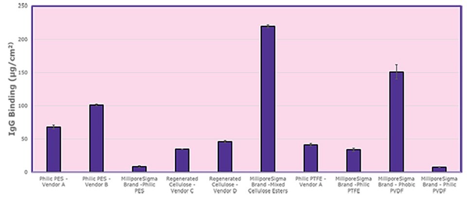
Figure 1. Protein binding comparisons of Millipore® and competitor 25 mm cut disc membranes with calculated standard deviation error bars.
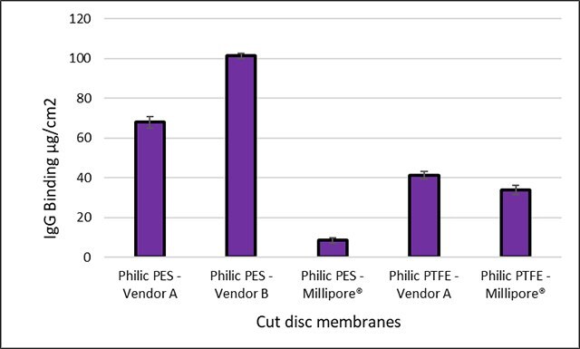
Figure 2. Protein binding comparisons of Millipore® and competitor 25 mm cut disc membranes with calculated standard deviation error bars.
To continue reading please sign in or create an account.
Don't Have An Account?